HIGUYS ANY CHANCE SOMEONE CAN POST A PICTURE FOR ME OF THEIR FUSE BOX I HAVE A DIFFICULT TIME UNDERSTANDING THE BLACK AND WHITE DIAGRAM , CHEERS

 Low Range
HIGUYS ANY CHANCE SOMEONE CAN POST A PICTURE FOR ME OF THEIR FUSE BOX I HAVE A DIFFICULT TIME UNDERSTANDING THE BLACK AND WHITE DIAGRAM , CHEERS
 Overdrive
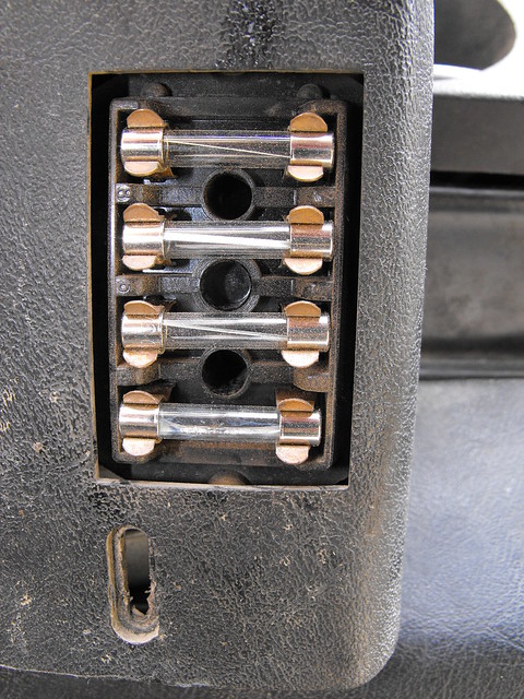
I'd post a picture of mine, but all you're going to see is a rectangular hole with 4 fuses in it.
--Mark
1973 SIII 109 RHD 2.5NA Diesel
0-54mph in just under 11.5 minutes
(9.7 minutes now that she's a 3-door).
 5th Gear
WHAT SEEMS TO BE THE PROBLEM? ARE YOU LOOKING FOR IT'S LOCATION OR THE FUNCTION OF EACH FUSE? IF YOU HAVE THE GREEN BIBLE, IT SHOULD HAVE A KEY/TABLE WITH THE COLOR CODE FOR EACH WIRE TO HELP DECIPHER THE BLACK AND WHITE DIAGRAM.
hope this helps and good luck!
-Rob
Overdrive
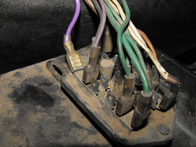
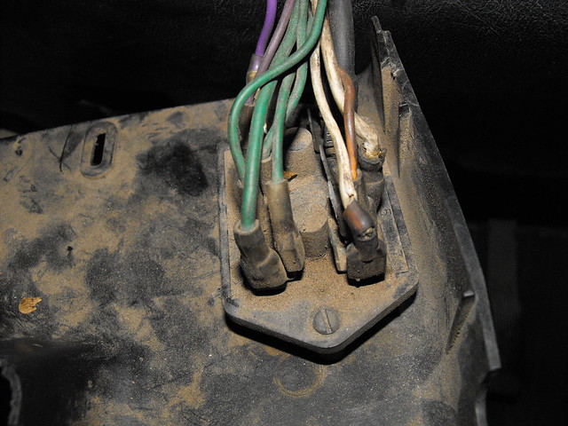
HERE'S THAT PIC OF THE FUSE BOX IN MY 73 SERIES III:
--Mark
1973 SIII 109 RHD 2.5NA Diesel
0-54mph in just under 11.5 minutes
(9.7 minutes now that she's a 3-door).
 2nd Gear
add a few more while your mind is in the electrical mindset. Rover went all out when they doubled the fuse count to 4 with the series three, but thee really should be a few more..
http://www.amazon.com/Painless-17204...176437&sr=1-16
ROB AND MARK ABOVE ARE TOP NOTCH GUYS THEY'LL HELP YOU OUT IF YOU ASK MORE SPECIFIC QUESTIONS.
STEVE
---- 1969 Bugeye ----
---- 1962 Dormobile ----
 4th Gear
THANKS FOR HELPING THIS GUY OUT, GUYS.
 Overdrive
I ended up leaving the stock wiring pretty much alone but did add a seperate fuse block for accessories. I believe I added 8 circuts not counting the seperate circut for the glow plugs. I also added seperate relays for low and high beam headlights and the work light. The new fuse block and the glow plug relay is all tied onto the positive post on the battery. It was fairly easy once I got my head around what I needed to. The Green Bible is almost necessity to be able to understand how things get their power and where to ground them.
Jim
Overdrive
Ok now that we're done messing around with you for using ALL CAPITAL LETTERS IN YOUR POSTS (well, except Jim, who didn't mess around with you), here's what you want to know...
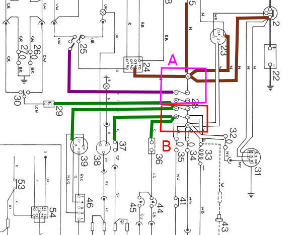
If you take the SIII schematic and rotate it a quarter-turn clockwise, you'll get the image you see when you dangle the fusebox down from the steering column.
As you're looking at the dangling fusebox, all the connections on the RIGHT side are connections BEFORE the fuses--In other words, these are NOT protected by a fuse at all. This is the side where the 12 volt power is supplied to all the circuits.
All the brown wires are connected to the top right-most terminals as you look at the dangling fuse box--these wires are ALWAYS hot with 12 volts, no matter what position the ignition switch is in. This is also where the ignition switch gets its power.
There's a brown wire that feeds 12 volts from the battery (post on the starter) to the upper right corner of the fuse box and then, through another brown wire, to the ignition switch.
On the upper right corner of the dangling fusebox, there's also the wire that goes to the horn, to the test socket and, sadly, to the light switch. These are all circuits that get their power BEFORE the protection supplied by the fuse.
Now the LOWER right corner of the dangling fuse box gets it's power from the fat white wire when the key is in the "run" or "start" positions. In other words, power to things like the coil, oil pressure light, turn signals, etc, are only supplied with electricity (at the bottom right corner of the dangling fusebox) when the key is on or you are cranking the starter.
The other white wires that come from the lower right corner of the fuse box supply the power to such things as the coil, the oil pressure switch, the charge light, the choke light, and the fuel and temp gauges.
I don't know why the engineers elected NOT to fuse these circuits with the white wires, but they are all drawing their power BEFORE the fuse, so they are COMPLETELY unprotected.
OK, so that's what's hooked up to the RIGHT side of the dangling fuse box--the circuits that are UPSTREAM of the protective fuses.
On the LEFT side of the dangling fuse box are the circuits that are DOWNSTREAM of the fuses, meaning that if these circuits short out, the fuse will blow, cutting off power to the downstream part of the circuit, avoiding a potential fire.
On the upper left side of the dangling fuse box are those items that are always hot AND protected by the fuse: The high beam (purple) wires, specifically.
At the lower left corner of the dangling fuse box, you have the pack of green wires. Generally, green wires mean "hot with the key in the run or start" positions, which energize things like the gauges, turn signals, the brake lights, and what-not...
The heater on mine seems to be hooked into the lower right part of the dangling fuse box, drawing it's power right off the "hot in run/start" wire BEFORE it gets the protection of a fuse.
Um...That's about it. Hopefully you can make sense of all the stuff above. If not, just ask some specific questions, preferably NOT IN ALL CAPITAL LETTERS, or else we'll have to mess with you some more before we get to the answers
Disregard the boxes depicting "A" and "B" in the diagram below, but note that the top most fuse in the dangling fuse box is ALWAYS hot and the bottom 2 fuses in the dangling fuse box are hot in "run" and "start." Odd, but there's nothing normally connected to the 2nd fuse down in the dangling fuse box.
It's difficult to depict a white wire on a white page, but if you look carefully, I've put thin black lines outside of the white wires to the fuse box in the schematic below to highlight the white wires:
.
Last edited by SafeAirOne; 07-20-2013 at 12:06 AM.
--Mark
1973 SIII 109 RHD 2.5NA Diesel
0-54mph in just under 11.5 minutes
(9.7 minutes now that she's a 3-door).
 2nd Gear
Few of those wires on the power in side look like they got a little crispy at one point in time! Very good explanation on what is what.
Overdrive
Umm....No comment.Originally Posted by ArlowCT


--Mark
1973 SIII 109 RHD 2.5NA Diesel
0-54mph in just under 11.5 minutes
(9.7 minutes now that she's a 3-door).
 Posting Permissions

 Reply With Quote