painless wiring harness is also an option. You could get a couple of more circuits and newer fuse panel.


 Low Range
painless wiring harness is also an option. You could get a couple of more circuits and newer fuse panel.
Sean
1971 Series IIA Dormobile
 Overdrive
The wiring diagrams in the work shop manual are a sampling of circuits for different year vehicles built to different country specifications for different models. If you want the correct wiring diagram for your vehicle look in the owner's manual. Unlike most owners manual the Series manual is actually useful with the correct wiring diagram, step by step tune up how-to instructions and a maintenance schedule chart.Originally Posted by cedryck

When I was new to my 1960 109 having the owner's manual was a big plus. It was also very interesting to read about the available options. I had no idea that an alternator was a factory option in 1960.
wire colour code chart
Fuse equivalent chart, US vs UK fuses
Early headlamp /ignition switch connections
-
Teriann Wakeman_________
Flagstaff, AZ.
1960 Land Rover Dormobile, owned since 1978
My Land Rover web site
 3rd Gear
Listen to Terriann and O2batsea when it comes to cost and how to do it. I'm currently building a new wiring harness for my daily driver, but the way I'm doing it, is I measured the truck up, and mocked the engine compartment and dash area up with peg board, the type you hang your tools on. I'm going by the diagrams in the book, and referring back to my truck for anything that doesn't seem to match up. One thing that I'll mention getting that no-one else mentioned yet are heat shrink connectors, these are great as they also give you weather proof connections on your wire ends. When I'm done, I'll have a wire harness that matches the British standard color codes that can just be dropped it, with a new multicircuit fuse box and relays for the headlights. As for the gauge and sizes of the wires, I believe Terriann has that in her website if I'm not mistaken.
Harvey
 Low Range
This is quite an old thread to resurrect, but I wanted to ask a few quick questions on this. Got the harness from the host for a '64 '88 positive earth converted to an alternator configuration.
Main harness is relatively easy.
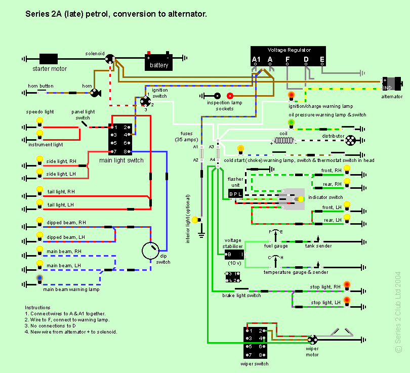
can anyone point me in the direction of a diagram with the alternator conversion. I have the green bible in triplicate, but can't seem to find that specific config.
Heres as more detail ( having a hard time orienting the main secondary harness. On one end it has large two female spade clips on heavy brown wires (ammeter? So in the cab?) and a yellow with a spade clip. Shortly after that branch out to a green solid with a female spade.
I guess a better way of asking the question is does anyone have a wire harness that goes around the front of the engine? I can't seem to figure out how it lays out and stays on the back by the fire wall. Thanks in advance. I know this is a horribly asked question.)
thanks!
3rd Gear
Well I can help with the diagram for the alternator conversion, all the diagrams you could need are here:
http://www.series2club.co.uk/forum/f...c,58789.0.html
 5th Gear
that is a great colored diagram,
Low Range
Awesome! Thank you very much. I think what's throwing me is that it's the alternator harness and the clips are different. Now that I have that figured out, I can use the above diagram ! Thanks
 Overdrive
You do not need to keep the Lucas voltage regulator in the mix. It can go into the trash can of history.
I don't know about your harness but am not too happy about having ALL the lighting circuits (green wires) coming off one fuse. I broke mine down into instrument, interior, accessory and other circuits that have their own fuses. The white switched power wiring also has its own circuits for things like the senders (yup it's fused too). Also, diagrammed above shows virtually no wiring protection for the headlamp circuit. Kinda scary by today's standards.
However if you are shooting for keeping things original, then I guess you're OK as long as you don't try to overburden what's there.
Remember, fuses protect WIRING, not the thing at the end of the wire that's doing the work.
So they prevent having major meltdowns of your harness.
5th Gear
I purchased a harness from, Auto Sparks. I can go back into my archives and get an address and contact. They will make anything you want, and frequently do Landrover series harnesses. Plus they support the headlight circuit with modern stlye relays, and plug in fuses. Bonus. The harness our host have is nice also.
 RN Sales Team - Super Moderator
Try this, from our hosts :-
http://www.roversnorth.com/info/WebsiteInfo.aspx?fc=35
Les Parker
Tech. Support and Parts Specialist
Rovers North Inc.
 Posting Permissions

 Reply With Quote