


Hello Rovers!
I am in the middle of a single-line to dual-line plus Power booster upgrade on my 1973 series 3, 109" RHD truck. I'll do a comprehensive post when I'm done as I think people might find it interesting to see the costs and challenges. But here's a little one to give folks some initiative:
I have been scouring the parts catalog and all the usual vendors(including our hosts) in this list:
https://forums.roversnorth.com/showt...-a-small-world
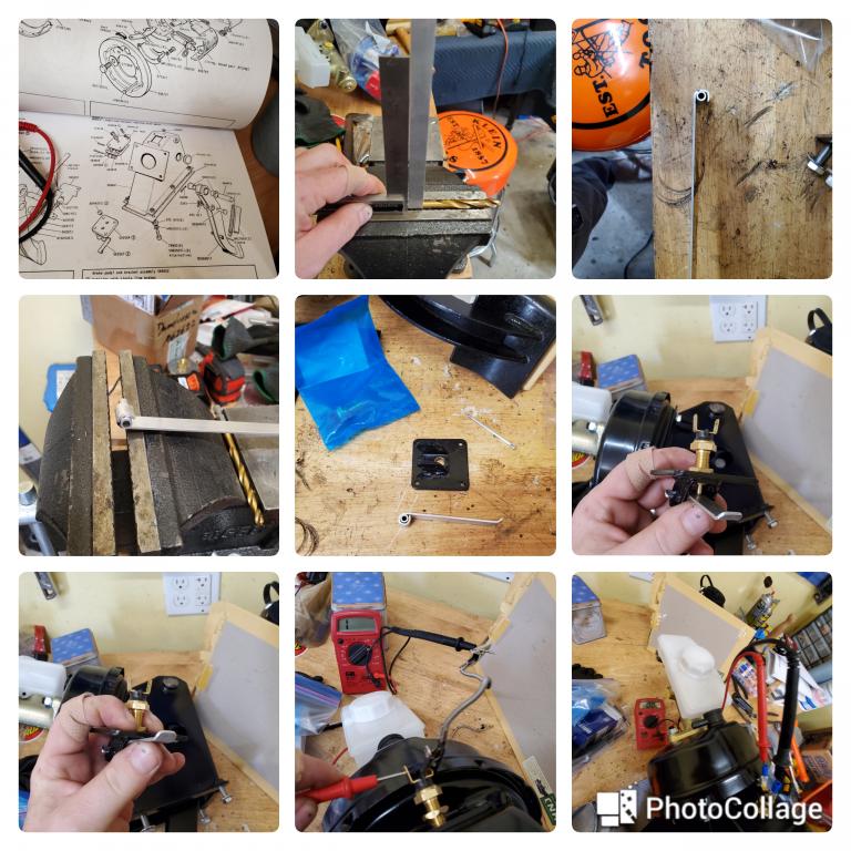
...and no one seems to make part#592567! It's a little spring arm that levers up and pushes the brake switch on the power booster brake tower.(See my image from the Parts catalog). Such a tiny, insignificant part...but it stops the build!
After your encouragement on my last discontinued part, I decided to fabricate one! If you have this same problem, here is a breakdown of the steps. Took about 30 minutes and let me continue the build.
1) Source a piece of steel or aluminum stock, about 3/4 inch wide and thin enough to bend/shape on the vise, but not bend by hand. Use the hinge fitting on the plate (AEU 1468) as width.
2) Also, get an aluminum spacer or small tubing to keep a nice round fulcrum for the new spring arm. Home Depot has both of these.
3) Use vise to clamp about 1/4 inch of aluminum stock. Use a carpenter's square so you know you are clamping exactly 90 degrees, or you will roll the aluminum like a cresant roll and be unhappy.
4) Use a hammer and roll it 90 degrees.
5) Get a drill bit of approximately the same size/radius as your round stock spacer. Clamp it into the elbow of the bend you just made, in the vise. Use the square again to make sure your stock is 90 degrees in the vise jaws.
6) Use hammer or vise to press the aluminum stock around the drill shank, forming a round over that the little tubing can fit in.
7) Put the tubing/spacer in the newly formed round fulcrum. Congratulations, you've made a tiny leaf spring! Use the vise and hammer to tighten up the fit, being careful not to crush the tubing and make it come out-of-round.
8) Cut the width of the tubing to match the inside of the hinge hangers on the plate. Put it in there and use a Cotter pin to secure it in.
9) I had no idea of the length, so I cut it long. You can trim it later. The final length is about the same width as the mounting plate(see parts catalog diagram). You should also put a slight bend at the end to make it easier to install in the brake tower.
10) Test fit. I had to remove the vacuum diaphragm to install it. There just wasn't enough space to get the plate on and even reach the front 2 mounting screws with the diaphragm on. This was easy for me with new parts on the bench, but would be annoying in the car. Watch those tiny screws! You drop them and they vanish from the universe...
11) Adjusting and testing. After I assembled everything and screwed the new switch in, it didn't really have the range of motion I expected. I mean that the action of the brake pedal didn't lever that little are as much as I thought it would. That image with my fingers cycling it...yeah, it only goes through about 1/4 that range installed in the tower. So, that means it's about proper adjustment to get the switch in the right range.
12) I hooked up a voltmeter and set it up to measure resistence(Omega setting). The next part is finicky, because you need 4 hands. But, some lead clips or female electrical connections help hold things while you move the brake pedal. This might be easier installed in the car, but I did it at the bench in case I had to disassemble everything again. Luckily, it was not that bad, and just involved spinning the switch in or out until the range of motion matched the open-close circuit of the switch. It was a bit tight. The actual range on the brake switch is about 1/2 turn. So, if it's in too far...the brake light would be on the whole time. If it's not in far enough, the light never comes on. That difference is a half a turn. So, I backed it off a 1/4 turn and got it in a decent t range. I'm still not happy with it...so I'll adjust it further on the car, with the lights powered and the brake lines full and pressurized. Right now, on the bench, I have to push the pedal down almost 1/2 way through for the light to switch on. That feels excessive...maybe might not come on in light tapping. But then again, it may feel different in actual use. I used to have to hammer on my old leaky brakes to even do anything, so it's probably reasonable on Series trucks that you're half way through the travel of your brake pedal before it starts grabbing. I can adjust when I get it in the car. Just mentioning it here as a "pre load" kind of step...just getting it "in the ballpark" before final assembly.
So, that's it! It works. There are two other places for these brake switches, depending on your package options. Folks with single line systems will have an in-line pressure switch at one of the front junctions. Also, the non-booster brake tower has a switch at the front of the pedal, like modern cars. I was going to do that, if this didn't work. But trying to keep things stock and somewhat matching the parts catalog. So far, I'm happy with it. So if you have a similar need, you can try this.
Oh, also need to mention that the booster brake tower is a repro one fabricated by Pangolin4x4 as its also a discontinued part (but available at their website).
Now for pics!
 __\\_____
 Reply With Quote