Thanks @roverp480 and @jimrr
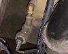
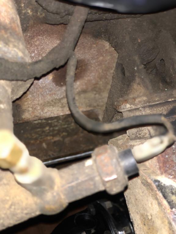
roverp480, Thx for p/n and oil sender location confirmation, as well as oil light wire info. In answer, the vertical brass looking bit is just a capped off post (better pic attached in this reply). I'll consult wiring diagram since I see sender is two prong, but only one wire seems to go to oil gauge from engine bay (pic 3 above, green/brown in black sheath). Perhaps one prong is ground? Anyway, it seems the vertical post just needs replaced by the pressure sender, along with attaching the green/brown wire to it, agreed?
jimrr, I believe it's 10V to the gauges, via voltage stabilizer I recently replaced. Thanks for the ground tip, which I did today, and both the engine temp and oil pressure gauges pegged respectively. Wiring/gauges seem all well, thankfully. Next I'll install the LR engine temp sensor I have, connect the wire, and cross my fingers. Will antifreeze flow out of the temp sender hole when I remove the current plug?
I'm stumped as to why it was set up as it is (ie: temp gauge wire routed to oil pressure gauge, and temp sensor removed altogether), but many thanks to you both for helping sort it...


 Reply With Quote

