-
 locking strip
Great, thanks for the tip: that is just the info I needed. The spring I use doesn't really hold the screw very securely in place. I saved the nylon strip and will put it back in. Thank you!
EDIT: added the nylon strip back into the groove and it really holds! Definitely worthy of the patent that it received!
But I still have the dieseling...
Last edited by PavementEnds; 10-17-2011 at 08:42 PM.
-
Zenith 36 IV ventilation screw #29 and anti-dieseling solenoid?
Have been trying to get to the bottom of the dieseling. Looked at several of the Zenith 36 IVs that I have and only one of them retains the ventilation screw (#29 in the Service Bulletin, hole shown in 1st photo) that connects upwards to the economy device. The bore of the screw is only slightly smaller than the bore of the hole and I am wondering if POs decided to remove this screw because they did not find it required? It is not supplied with either of the two rebuild kits I have purchased. I have one of these screws.
On the anti-dieseling solenoid, two of my carbs have a low position near the idle screw (2nd photo ) while the third has a high position (3rd photo) above the idle screw. Does anyone know if there is any difference between these two? Is one preferred over the other? The one currently installed, the high position, does not completely stop the dieseling so I'm thinking to try one of the low position carbs.
-
Yearly update
It has been nearly a year since my last update on the rig. Bottom line is that it is now running just fine, but the getting it there has taken some effort
Distributor. If you read back through this stream, I was having problems with tuning and could never get the engine to run just right. My rig is a 1973 and came with all of the new emissions equipment, almost all of which had been removed by the PO (he told me it was worthless and pulled it and threw it away). The PO was a packrat like me, and in going back through the receipts and other printed materials I found information about the emissions system. This info pointed out that these rigs were fitted with a special distributor. I remembered an earlier thread here about a Lucas distributor (just looked for it and couldnt find this thread) in which the writer noted that its vacuum advance pointed toward the front of the engine compartment, unlike most distributors, and this was also the configuration of my special distributor. The emission system included a second vacuum unit with what they called the carburettor throttle-prop system and this was part of what the PO had removed. So, since the other half of this system was missing, I thought this might be part of the problem and decided to buy a new distributor with its vacuum advance pointing to the rear of the engine (that is, the one designed to run without the emissions system). I had earlier installed a Pertronix system in the existing distributor (which helped some, mostly because I found that the replacement ignition components [rotor arm, condenser, points] were of low quality) but this Pertronix model did not fit the new 45D so in the end I decided to fit a full replacement Pertronix distributor (D176600) since its price was about the same as a new 45D + new Pertronix. My suggestion to anyone with a rig that dates from the early 1970s and might have the special distributor but not all of the other emission equipment is to look into buying a regular distributor.
Carburetor. I had the usual problems with the Zenith 36 IV carb (warping, knackered idle mixture screws, float with a hole in it, bad accelerator pump piston, a missing #29 ventilation screw, etc.). I got an old carb from Terrys (much appreciated, as is his maple syrup), another from Les Parker, and used the Terrys carb with the Les emulsion block, lapped the halves, and rebuilt a carb that now works. I installed the fuel anti-dieseling solenoid and this has ended the dieseling.
Tuning. Checked valve clearances and most were out so reset all to 0.010. I used the Mityvac attached to the vacuum on the intake manifold to set the timing and this worked like a charm. I had never tuned with a vacuum meter before, and by adjusting the distributor advance and carb settings managed to get the vacuum needle to sit very steady at 19+/-1; playing around with settings showed just how far off the timing could be, and why (see http://sbftech.com/index.php/topic,3020.0.html). My two multimeters still give two different readings and I dont know what is going on there! Setting is at 7 degrees BTDC and RPMs at 760-780.
Hot tub. In earlier posts I noted that the exhaust system and the tub were running really hot. Getting the tuning correct re. the correct distributor and correctly rebuilt carb lowered the temps all around.
Exhaust system. This finally gave up the ghost which is not unexpected after nearly 40 years. Most of the system was intact but it had rusted out at the exhaust manifold connection to the downpipe. I ran into the typical problems on attempted removal of the frozen nuts and studs. I tried the usual methods (lots of PB Blaster for a week, red torch, melting wax onto the threads, etc.) but still managed to remove only one nut and break two studs. My remaining option was to remove the exhaust manifold in order to drill out the studs but recurring nightmares of more broken studs shook some sense into my head and so I punted and took the rig to a muffler shop and for $60 per stud they removed and installed the new studs. Other than the rebuild of the alternator and turning the brake drums, this is the only outsourcing Ive had to do, and it was all done on American soil, ha ha! It was well worth the cost. Needless to say, I used liberal amounts of anti-seize grease on the brass nuts.
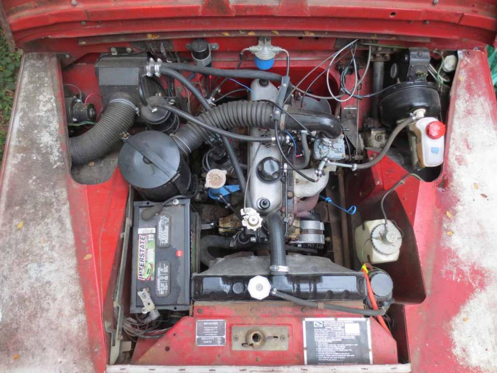
Other bits. Special ordered brass connectors from Grainger and built my own axle extension breather pipes. Tracked down a loose wire that I could never figure out and found out that it was for the 2nd speed of the windshield wiper. The wire for the washer was also broken off. I reconnected this wire and it works but it looks like the lines or nozzles are plugged because the water only dribbles out this fix remains to be completed but at least I know what is wrong. Got the common symptoms of a jumpy speedometer needle. I pulled the instrument panel and in trying to remove the speedometer cable manage to break the (=40 year old) plastic tab that secures the end of the cable to the recessed keeper groove on the speedometer housing. I oiled the cable and drilled a small hole in the end of the grey plastic cable housing so that I could thread a small screw in there with a lock washer and then use this assembly to secure the cable to the keeper groove of speedometer housing. This connection provides a tighter fit than the plastic tab but I have found that I need to oil the cable every 6 months or so. The finish on the steering wheel began to disintegrate into the commonly reported brown goop and so I sanded it down, filled the numerous cracks with JB Weld, and repainted and sealed it. It looks great now and no more brown sticky hands. Traced a rain leak to a faulty (=40 year old) seal between the windshield and bulkhead and punted and used silicon sealer from a tube (for now) and that stopped the leak. Ordered new seat bases from site sponsors and man oh man do they ever dress up the rig! I bought a piece of horse stall matt from Tractor Supply and one matt supplied enough material to make matts for the front and rear. I cut the matt with a box knife and am happy with the result. It deadens some of the noise up front and it gives the black labs better traction (and a cooler floor) in the rear. I should post my cut-out patterns for the front. I discovered the hard way that the fuel gauge only works part-time... one more thing to repair. Finally got around to checking out a persistent leak from the transmission cover and found that all of the studs and nuts were loose. I dont know why I had never checked these for tightness. I cut a new gasket, reinstalled the cover, tightened the studs and nuts, and the leaking is greatly reduced. Mostly recently, just this week in fact, was driving down the alley and the neighbor lady who has a blind exit from her garage backed into us. No serious damage, but in my uncoordinated rush to hit the horn I pushed the switch arm forward too hard and the (=40 year old) plastic ring that connects the upper turn signal switch to the lower pivot pin sheared loose. No turn signals, no high beams. I took off the steering wheel, took the switch apart, and drilled some small holes into the top and bottom of the housing and then used wire to tighten up the fitting across where it was cracked. (Photo shows the repair, but the legged spring is shown as too far forward and has to be reset back into the switch so that it that makes the turn signal connection.) Ive ordered a new assembly but this jury-rigged fix works for now.
So, this is my 12 month update. I use the rig as my occasional driver, trips to work and down to Austins Lady Bird Lake running trail and I often get the sweet ride and thumbs up comments. Now that this 1973 S3 is running (statement followed by the proverbial knock on wood
), I have started a rebuild of a 1951 Series 1 that I picked up in June 2012 (http://forums.roversnorth.com/showth...-1951-Series-1). This old rig appears to be original re. the serial numbered parts but has 60+ years of POs fixes that will require some attention. Parts are definitely more difficult to come by, but the chase is, for now at least, part of the fun!

Last edited by PavementEnds; 10-13-2012 at 12:17 PM.
-
Finally opened up the dash to replace the broken turn signal switch with a new one. The wired-up fix worked fine except that the switch for the low to high beams was stuck on high. The new switch wired up just fine, and I'll keep the old one as a spare. The main reason though for opening up the dash at this time was that the speedometer had stopped working again. I figured that the cable needed another oiling and did that, buttoned it back up, but found that it was still not working. So, I removed the 3 dreaded slotted screws that attach the cable at the gearbox and discovered that the cable had broken about 12" into its length. As anyone who has replaced the cable knows, this repair is a bit more involved than it looks. I had a new cable on hand and replaced the 3 screws with 10/32 Allen head bolts but these are only slightly easier to get to; main advantage is that they don't slip off the Allen key in the way that the little slotted screws slip off a screwdriver. This is not a job I want to repeat anytime soon!
-
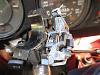
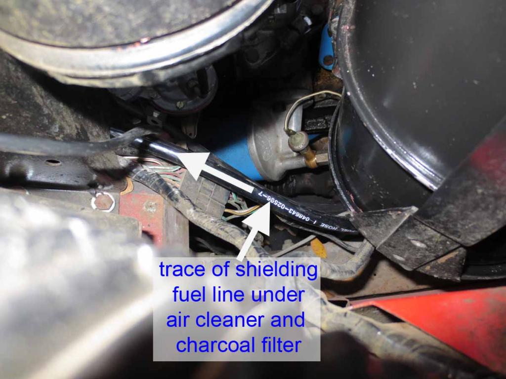
The original electric oil pressure sensor finally gave up the ghost so I decided to add a capillary (mechanical) oil pressure gauge. I have what appears to be the original fittings coming off the original canister oil filter, with a banjo fitting for the oil pressure warning light, and the electric oil pressure sensor on the end of the assembly. I bought a Sunpro (CP8216) gauge ($20, included nylon capillary line, compression fittings, and light) that is the correct diameter to replace the original Smiths gauge. The hard part was finding a 1/2"-20 tpi adaptor to accept the 1.8" NPT compression fitting. No go at Pep Boys where I bought the new gauge, no go at Grainger, but Austin's Hydraulic House had the fitting for $5. I used new copper washers at all connections. The nylon capillary line looks pretty tough but I decided to use fuel line to shield the nylon line. I snugged the shielding line right up against the compression fitting and attached another 2" length of heater hose and 2 hose clamps over the top so I could protect the connection and keep things in place as the line makes its 180 degree turn back toward the bulkhead. The line follows a path under the air cleaner and charcoal filter and up into the bulkhead and follows the same route through the dash that the wiring harness follows. I left a small coil of nylon capillary line in the dash at its exit from the shielding line, and used the compression fitting to attach the line to the gauge. The original light fits into the new gauge so I did not have to use the new light. There is also a small grounding wire to attach to the gauge. I fired up the engine and the gauge works great, registering 45 PSI at idle.

-
Floor and cargo mats for a 1973 Series III SWB 88" LHD
I used a 4' x 6' horse stall mat from Tractor Supply to make floor mats for my 1973 S3. A mat costs $40 and provides an economical option to the commercially available mats. A single horse mat provides enough material to make one each of a driver, passenger, and cargo floor mat. The most challenging part of this job was making the patterns. I fashioned them from newspaper and then laid them out on the mat so that the straight edges of the patterns took advantage of the straight edges of the stall mat and thus reduced the number of cuts that were required. I used a sharp utility knife for the cuts and even though I had to go over each line several times to complete the cut, the knife proved to be cleaner than using a saw. The mat is 3/4" thick and it helps to insulate from the heat and sound and has proven to be very durable.
In the event that others would like to try this project, I transferred the patterns to pdf files that can be printed out in Adobe Reader (program freely available from http://get.adobe.com/reader/) using the "tile" function with the option of "cut marks" and printed at a scale of 100% on 8.5 x 11" paper. The composite pattern is produced by lining up the cut marks in the corners of each page and taping the pages together. The patterns are next cut out along the outside of the perimeter lines. The driver and passenger patterns must be placed on the full horse mat in a particular orientation in order to leave enough material for the cargo mat, and I also made a layout sheet that illustrates these orientations. The cargo mat is 36" x 47.5" and does not require a separate pattern. I would recommend laying the patterns out on your floor before cutting the stall mat just to make sure that the patterns printed out at the correct scale. The mat is heavy and a bit cumbersome to muscle around so you might want a second person to help load and unload.
I am at my maximum for my attachments allotment so if you'd like me to email you the patterns, just PM me and I'd be happy to do so.
Good luck!
 Posting Permissions
- You may not post new threads
- You may not post replies
- You may not post attachments
- You may not edit your posts
-
Forum Rules


 Reply With Quote