

 Tweet
Tweet
Don't groan too loudly 
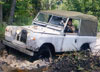
Many of you know I picked up this 109 that was converted to diesel just before I deployed and am working on getting her into running condition. The alternator had been installed, but I don't think it had been wired properly because I've got a charging issue that I'm really interested in working out.
I've looked at countless diagrams and suggestions, have had electric-smart people over to help me pore through it but each time we come up empty ... the thing just won't charge.
The alternator and battery have been ruled out and tested.
Basically on the voltage regulator I have more wires and spades than depicted on wiring schematics and diagrams so that's thrown me for a loop.
A1 - two wires jumped together - one goes to the light switch on the dash, and the other to A1 fuse.
A - only one wire here where my diagram shows two - the one wire goes to the red inspection socket. Since the other wire that should be there would go to the horn it would explain why the horn isn't working.
F - goes to charge warning lamp and the oil pressure warning lamp - these two are jumpered together as well.
D - goes to Amp meter.
On one of the smaller back spades there is also a black wire that leads who knows where. The vehicle runs just fine, just doesn't charge. If I leave the battery on the trickle all night she fires right up. A few times later in the day though if I start her up she'll fire up just fine, and then if I turn her off and then go to restart her minutes later she won't budge without a jump.
I'm hoping somebody has some answers. What I'd really like to do is circumvent the regulator entirely, but don't know if that's an option. After pulling the regulator I do know it's bad as one of the metallic strips is blown through.
ANy help or a highly detailed picture of what I need to be doing would be greatly appreciated.


Comment